17.4 Pin Connectors and Channel Mapping
We encountered FX pin connectors and channel mapping earlier in this User Guide, in Chapter 7.
Kind: concept (user-guide-section) Chapter: 17 More Routing Examples Source: REAPER User Guide v7.70
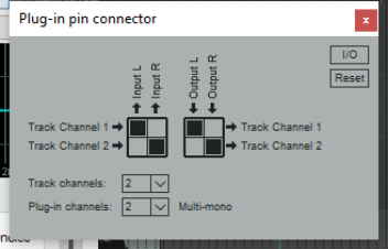
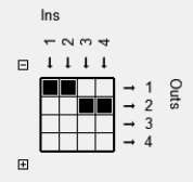
We encountered FX pin connectors and channel mapping earlier in this User Guide, in Chapter 7. Channel mapping is accessed by clicking on a plug-in’s In/Out button (typically labelled 2 in+out). The pin connectors are like virtual cables, used in your FX to determine the channels that are used for the audio signal flow. This is shown in the pin connector interface. Study the arrows and the black squares in the diagram (right). These indicate from which track channel(s) the audio comes in to, and (after processing) goes out of, the FX. The first grid shows two separate audio streams from the track being input into an FX, from channel 1 (to the FX left input) and from channel 2 (to the FX right input). The second grid shows the output from the left FX channel passed to track channel 1, and from the right FX channel to track channel 2. What happens in between input and output is determined by the FX and its parameter settings. Depending on the particular plug-in, you might have a choice of channel modes. These are explained in Chapter 16 in the context of ReaComp. For example, ReaComp and ReaGate support stereo, multi-mono and multi-stereo modes. ReaEQ and ReaVerb support stereo and multi-mono modes. The JS Channel Mapper Downmixer, as its name implies, mixes channel inputs as required before passing the signal “downstream.” Before looking at an example we need to understand a little more about the interface. By default, REAPER tracks comprise two channels (left and right). However, if the track has more than two channels then these channels will also be displayed in the plug-in pin connector.
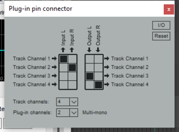
The track channels dropdown can be used to increase or decrease the number of channels in the track (e.g. from 2 to 4 or 6): the plug-in channels dropdown defines the number of channels available in the plug-in. Remember that signal flow is sent from inputs to or removed from outputs by clicking in the boxes where the input/output combination intersects. In the example below, the track has four channels, but the plug-in has only two. The signal enters the FX from track channels 1 (L) and 2 (R) and after processing passes out to track channels 3 (L) and 4 (R). This configuration can also be managed from the I/O menu (Audio input/output, MIDI input/output, plug-in channel configuration). Help is also available on this menu. Other I/O menu options include:
Delta solo (difference between dry and phase inverted wet). Toggled on/off by pressing Alt click on the FX wet/dry mix control. Allows you to hear only the difference a plug-in is making to the signal. Examples might be when soloing EQ bands to assess their effect, or when adjusting threshold, attack and release settings in a compressor. PDC: whether to apply plug-in delay compensation. Pass thru unmapped output channels or Zero unmapped output channel. Where a channel is not mapped (e.g. 1 to 1 and 2 to 2 in the second example above), whether to automatically pass the unprocessed signal thru to that channel. The Reset button can be used to restore some or all settings to their defaults, or to clear settings. Options are:
Reset all Reset input Clear input Clear all Reset output
Clear output.
Example
This simple example is not necessarily something you will want to do, but it illustrates how pin connectors and channel mapping work. In it, we will be adding reverb to just one channel of a track.
- Into an empty FX chain we insert ReaVerbate, display the pin connector and add two channels. Direct
output to 3/4, as in the example above right. The option Pass thru unmapped output channels is enabled so that the dry signal will pass thru this FX unaffected. 2. We adjust the reverb parameters as required. 3. The JS: Channel Mapper Downmixer is added after ReaVerbate. Set it up so
that the mixer channels 1/2 (dry signal) are passed to the track’s channel 1 (left), and 3/4 (wet signal) are passed to the track’s channel 2 (right). 4. We play the track, adjusting pan to suit, noticing that only the right channel will
include any delay. Headphones are a good way to test this!
The JS:Channel Mapper Downmixer
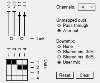
This contains interesting features beyond being a simple channel mixer. The options to Pass thru or Zero out act as explained above. There are also a number of options for adjusting downmix levels (see right). Of these, perhaps the most interesting is the User mix option. This will present you with a series of faders that can be used to adjust the volume levels of individual channels. Other options are None or -3dB or -6dB.